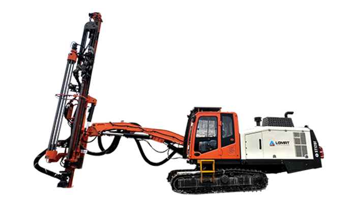
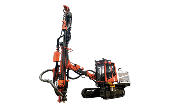
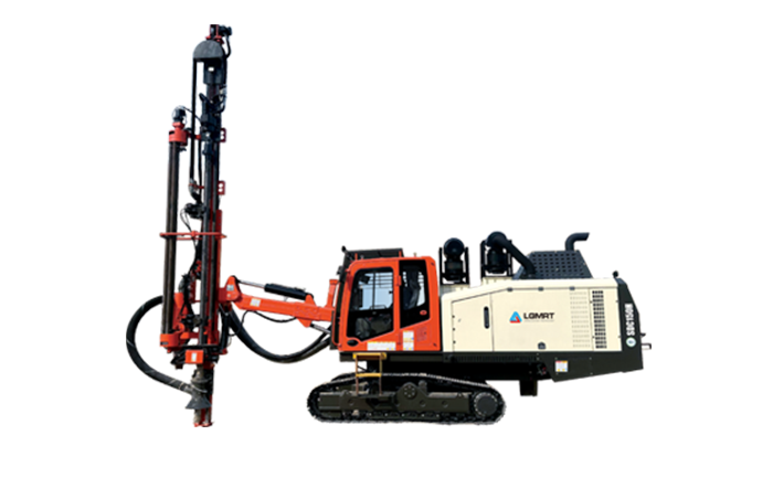
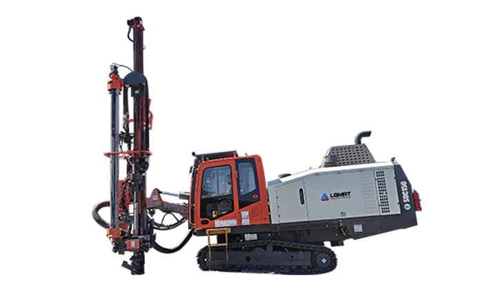
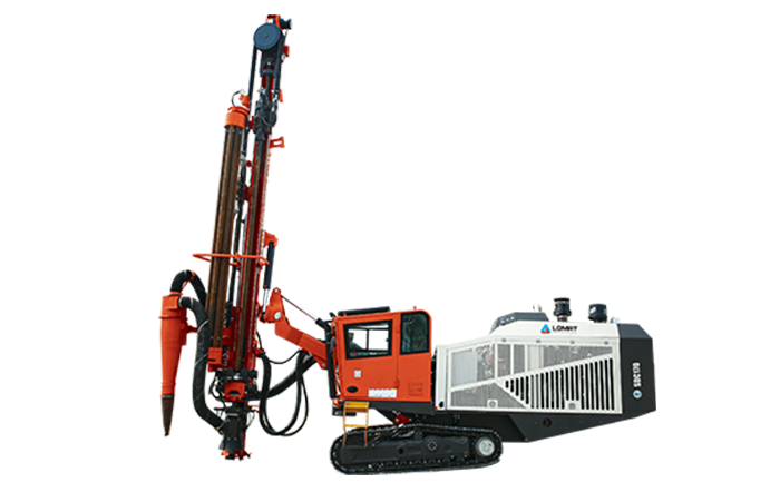
Development Drilling Rigs Supplier Haichuang Unite helps mining teams evaluate how automated drilling can reduce nonproductive time, improve hole placement, and create reliable drilling records for drifting operations. This guide explains the equipment, workflow, purchasing criteria, implementation steps, and common mistakes that affect automation results.

Understand the Operational Problems Automation Must Solve
Reduce the time lost between drilling cycles
In underground drifting, cycle time is often lost during activities that do not directly create a drilled hole. Operators may spend time positioning the rig, checking the face, measuring drilling depth, changing rods, recording parameters, and correcting holes that were drilled outside the planned pattern.
Automation improves cycle time by standardizing repeatable tasks and reducing manual adjustments. The greatest benefits usually come from better coordination between rig movement, drilling control, data collection, and operator decisions.
- Faster rig positioning at the face.
- Shorter setup and alignment time.
- More consistent feed pressure and rotation control.
- Reduced overdrilling and underdrilling.
- Less time spent repeating inaccurate holes.
- Faster transfer of drilling data to supervisors and engineers.
Improve hole accuracy in changing ground conditions
Drifting requires the drilling pattern to match the planned tunnel profile, face direction, burden, spacing, and required hole depth. Deviation can increase overbreak, leave unbroken rock, reduce advance per blast, and create additional scaling or support work.
An automated development drilling rig uses sensors, control software, and stored drilling plans to help maintain the intended drilling direction. Automation does not remove the need for operator judgment, but it gives the operator better information and more repeatable control.
Address the purchasing group's main pain points
Purchasing groups usually evaluate automation as a production investment rather than as a standalone technology upgrade. They need proof that the system will work with existing mining processes, operators, maintenance practices, and reporting systems.
- Unclear return on investment and uncertain payback time.
- Concern about training requirements and operator acceptance.
- Difficulty comparing manual, semi-automated, and fully automated rigs.
- Uncertainty about spare parts, software support, and service response.
- Concerns about integration with mine planning and fleet management systems.
- Limited underground communication and inconsistent data transmission.
- Fear that sensors will fail in dust, vibration, water, or high-temperature conditions.
- Difficulty proving whether productivity gains come from the rig or from other process changes.
Choose the Automation Functions That Directly Affect Drifting Performance
Use automated positioning and face alignment
Automated positioning helps the operator place the rig according to the planned face coordinates, drilling direction, and tunnel profile. Depending on the system, positioning may use onboard sensors, laser references, angle encoders, inclinometers, or a combination of these technologies.
The system should make it easy to verify the following information before drilling:
- Rig location in the heading.
- Alignment with the planned tunnel centerline.
- Drilling boom angle and direction.
- Hole collar position.
- Required hole depth and drilling sequence.
- Clearance from the tunnel wall, roof, and existing support.
Control drilling parameters automatically
Automated drilling control can regulate feed force, rotation speed, percussion pressure, flushing, and drilling depth. Consistent parameters help reduce unnecessary energy use and protect drilling tools while maintaining stable penetration.
Useful control functions include:
- Automatic feed control based on penetration resistance.
- Preset drilling depth with automatic stop.
- Automatic rod handling or assisted rod changing.
- Pressure monitoring for hydraulic and pneumatic circuits.
- Flushing control for improved cuttings removal.
- Real-time detection of abnormal penetration or tool behavior.
- Automatic recording of drilling parameters for every hole.
Connect automation with the drilling plan
The highest value comes when the drilling rig can use a digital drilling plan instead of relying only on manual measurements. The plan should define the location, angle, length, and sequence of each hole.
Before selecting a system, confirm whether it can import or export common mine planning formats. Also verify whether the system can operate offline and synchronize data when communication is restored. Underground connectivity should not prevent the rig from completing a safe drilling cycle.
Prepare the Required Tools and Information Before Installation
Required rig and measurement tools
A successful automation project requires more than a control screen. The following tools and equipment support setup, calibration, operation, and maintenance.
- Automated development drilling rig with compatible control software.
- Laser alignment device or underground surveying reference.
- Inclinometer and angle measurement equipment.
- Position sensors and boom feedback sensors.
- Depth measurement system or hole depth encoder.
- Hydraulic pressure and flow test equipment.
- Drill rod and bit inspection tools.
- Digital drilling plan or face design file.
- Rugged operator tablet or control panel.
- Underground communication or data transfer system.
- Calibration targets and reference points.
- Personal protective equipment and lockout equipment.
Required production and cost information
Purchasing teams should collect baseline data before comparing automation options. Without a baseline, it is difficult to measure whether the new system improves drilling performance.
- Average drilling meters per shift.
- Average time for rig tramming and positioning.
- Average time required to drill one hole.
- Average rod change and bit change time.
- Number of redrilled or corrected holes.
- Average hole deviation and depth accuracy.
- Explosive consumption per round.
- Overbreak and underbreak measurements.
- Operator and maintenance labor hours.
- Fuel, electricity, water, and consumable costs.
- Downtime caused by mechanical, electrical, or communication faults.
Required personnel for the project
Automation should be evaluated by a cross-functional team. A decision made only by procurement may overlook production, maintenance, safety, or integration requirements.
- Drilling and blasting engineer.
- Underground production supervisor.
- Experienced jumbo operator.
- Mechanical maintenance technician.
- Electrical and automation technician.
- Mine surveyor.
- Safety representative.
- Information technology or mine digitalization specialist.
- Purchasing and finance representative.
- Equipment supplier service engineer.
Follow a Step-by-Step Automation Workflow for Drifting
First step: Record the current manual drilling process
Document the existing process before making any equipment changes. Observe at least several complete drilling cycles across different shifts and ground conditions.
- Record the time required to travel to the face.
- Measure the time used for face inspection and scaling clearance.
- Record rig positioning and boom setup time.
- Measure the time spent marking hole collars.
- Record drilling time for each hole.
- Measure rod handling, flushing, and tool change time.
- Record interruptions caused by water, dust, ground movement, or equipment alarms.
- Measure the time required to check and correct the drilling pattern.
- Record the number of holes that require redrilling.
- Store the data as the baseline for later comparison.
Second step: Define the drilling accuracy target
Set measurable targets before selecting the automation package. Targets should relate to the actual excavation and blasting requirements rather than general claims about automation.
- Maximum allowable collar position error.
- Maximum allowable angle error.
- Required hole depth tolerance.
- Target drilling meters per shift.
- Target reduction in redrilled holes.
- Target reduction in overbreak and underbreak.
- Target equipment availability.
- Target data recording rate for completed holes.
Third step: Survey the heading and prepare the digital drilling plan
The survey team should establish the face location, tunnel centerline, grade, profile, and reference points. The drilling plan should then be created for the specific heading and round.
- Confirm the current face coordinates.
- Check the tunnel direction, grade, and profile.
- Identify geological or support-related restrictions.
- Define the collar position, angle, and depth for each hole.
- Set the drilling sequence according to the blasting design.
- Transfer the plan to the rig using an approved file format.
- Verify that the plan displayed on the control system matches the engineer's approved design.
Fourth step: Position and calibrate the rig
Calibration is essential because an accurate control algorithm cannot compensate for an incorrect machine reference. Calibration should be completed after major maintenance, sensor replacement, boom work, or collision damage.
- Inspect the rig for loose components, damaged sensors, and hydraulic leaks.
- Park the rig on a stable and reasonably level surface.
- Connect the rig to the approved underground reference system.
- Set the machine coordinate system.
- Check boom angle, feed beam angle, and rotation sensor readings.
- Compare displayed values with independent measurement tools.
- Calibrate the depth measurement system.
- Confirm that the first hole position matches the digital plan.
- Save the calibration record with the date, operator, and equipment identification.
Fifth step: Perform a controlled test round
Do not begin with a full production changeover. Use a controlled test round to identify positioning, sensor, software, and operator issues while the consequences are limited.
- Select a representative heading and ground condition.
- Review the drilling plan with the operator and supervisor.
- Drill the first few holes at reduced speed if required by the supplier procedure.
- Check hole collar position and angle after the first holes.
- Compare actual depth with the programmed depth.
- Review feed pressure, rotation, percussion, and flushing data.
- Stop the test if abnormal vibration, pressure, sensor error, or tool behavior occurs.
- Adjust the control parameters only after identifying the cause of the deviation.
- Complete the round and record the results.
Sixth step: Compare the results with the baseline
Review both productivity and quality. A faster drilling cycle is not an improvement if it creates excessive deviation, poor fragmentation, or additional support work.
- Total cycle time per round.
- Actual drilling meters per shift.
- Average drilling time per hole.
- Number of completed holes.
- Number of redrilled holes.
- Hole depth and angle accuracy.
- Penetration rate by rock condition.
- Consumable wear and replacement frequency.
- Operator intervention time.
- Equipment downtime and alarm frequency.
- Blast result, overbreak, and underbreak.
Seventh step: Standardize the approved operating procedure
Once the test results meet the targets, create a standard operating procedure. The procedure should explain what the operator must check before drilling, during drilling, and after completing the round.
- Pre-start inspection and safety isolation checks.
- Face and ground condition inspection.
- Survey reference verification.
- Digital plan loading and approval.
- Rig alignment and sensor calibration check.
- Drilling parameter verification.
- Alarm response and manual override procedure.
- End-of-round data upload and quality review.
- Maintenance reporting and fault escalation.
Use Data to Improve Accuracy and Reduce Total Cycle Time
Monitor the most important drilling performance indicators
Automation creates value when the collected data is converted into operating decisions. A dashboard should show trends rather than only display individual sensor values.
- Average penetration rate.
- Drilling time per hole.
- Average time between holes.
- Rig positioning time.
- Average hole depth variance.
- Average collar and angle deviation.
- Redrill percentage.
- Drill bit life and rod life.
- Equipment availability.
- Hydraulic and percussion pressure stability.
- Water and energy consumption.
- Round advance and excavation quality.
Use drilling data to identify ground changes
Changes in penetration rate, vibration, pressure, and flushing behavior can indicate changes in rock condition or drilling tool performance. The data can help engineers identify weak zones, fractured ground, excessive water, or worn tooling earlier.
When the drilling system detects an unusual pattern, the operator should follow a defined response process:
- Check whether the change affects one hole or several holes.
- Inspect the bit, rod, flushing line, and feed beam.
- Compare the current data with previous rounds in the same heading.
- Notify the supervisor if the condition may indicate geological change.
- Adjust drilling parameters only within approved limits.
- Record the event and the corrective action.
- Review the blast and excavation result after the round.
Calculate the financial effect of improved cycle time
The return on automation should include direct and indirect benefits. Purchasing groups should avoid evaluating the rig only by its purchase price or nominal drilling speed.
A practical calculation can include:
- Additional meters drilled per shift multiplied by the value of earlier advance.
- Reduced labor hours caused by shorter setup and recording tasks.
- Reduced consumable cost from better parameter control.
- Reduced explosives and secondary breaking caused by improved drilling accuracy.
- Reduced scaling and ground support caused by lower overbreak.
- Reduced equipment downtime from condition monitoring.
- Reduced survey and rework costs.
- Reduced safety exposure during manual measurements and corrections.
Compare the monthly benefit with the automation investment, installation cost, training cost, software fees, communication requirements, and planned maintenance cost. Use conservative assumptions and validate the calculation during a field trial.
Evaluate a Development Drilling Rig Before Purchase
Check drilling and automation specifications
Technical specifications should be matched to the mine's actual headings, rock conditions, drilling pattern, and production schedule. A high specification in one area may not compensate for limitations in another area.
- Applicable tunnel size and working envelope.
- Maximum drilling depth and feed length.
- Number of booms and boom coverage.
- Drilling diameter range.
- Available percussion and rotation performance.
- Maximum feed force and feed speed.
- Water and flushing requirements.
- Positioning accuracy and calibration method.
- Hole depth measurement accuracy.
- Sensor protection against dust, water, and vibration.
- Manual override functions.
- Emergency stop and safety interlock design.
- Data export and communication capability.
- Compatibility with existing drill rods, bits, and maintenance tools.
Verify operator usability
An automated system must be easy to use during a long shift in a confined underground environment. The control interface should show only the information needed for the current task while allowing authorized users to access detailed data.
Ask the supplier to demonstrate the following functions:
- Loading a drilling plan.
- Correcting a plan after a face change.
- Changing from automatic to manual control.
- Responding to a sensor alarm.
- Restarting after a power interruption.
- Saving drilling data when underground communication is unavailable.
- Exporting data for engineering review.
- Creating operator and maintenance reports.
Review service, training, and spare parts support
Automation performance depends on reliable service support. The purchasing contract should define response times, software maintenance, sensor replacement, training, remote support, and local spare parts availability.
Include the following questions in the supplier evaluation:
- How long does installation and commissioning normally take?
- Who performs calibration and acceptance testing?
- What training is provided for operators and maintenance staff?
- Which components are critical spare parts?
- What is the expected delivery time for sensors and control modules?
- How are software updates tested and installed?
- Can the supplier provide field service at the mine location?
- What performance data is included in the warranty?
- How are cybersecurity and user permissions managed?
- What is the total cost of ownership over the expected machine life?
Avoid Common Automation and Drilling Mistakes
Do not automate an unstable process without a baseline
If the mine does not understand its current cycle time, hole accuracy, downtime, and rework rate, it cannot identify the true benefit of automation. Establish a baseline first and use the same measurement method after installation.
Do not ignore calibration after maintenance
A boom repair, sensor replacement, feed beam adjustment, or collision can change the machine reference. Drilling should not resume at full production until the positioning and depth systems have been checked.
Do not rely on software without checking the face condition
A digital drilling plan represents the intended face, but the actual face may have changed after scaling, rockfall, water inflow, or partial blasting. The operator and survey team must verify the face before loading the plan.
Do not set drilling speed above the tool and ground capability
Excessive feed force or rotation speed can increase bit wear, rod stress, vibration, and deviation. Automation should maintain stable performance within approved operating limits rather than simply maximize instantaneous penetration rate.
Do not treat alarms as nuisance messages
Repeated sensor or pressure alarms may indicate a developing mechanical fault, a blocked flushing line, a damaged cable, or an inaccurate machine reference. Operators should record alarms and follow a defined troubleshooting process instead of bypassing them.
Do not overlook operator training and acceptance
Operators should participate in the trial, parameter review, and procedure development. If the control system is difficult to understand or does not allow appropriate manual intervention, operators may avoid using the automated functions.
Do not measure success only by drilling speed
The correct performance measure combines speed, accuracy, availability, safety, consumable cost, blast quality, and total excavation cost. Faster drilling with excessive overbreak may increase the overall cost of the heading.
Build a Practical Implementation Plan
Phase one: Define the business and technical requirements
- Select the headings where cycle time and accuracy are limiting production.
- Collect at least one complete baseline period of drilling data.
- Define drilling accuracy, productivity, availability, and safety targets.
- Identify required integration with survey, planning, maintenance, and reporting systems.
- Prepare a total cost of ownership estimate.
Phase two: Conduct supplier demonstrations and inspections
- Provide suppliers with representative heading dimensions and drilling plans.
- Ask each supplier to demonstrate positioning, plan loading, automatic drilling, manual override, and data export.
- Inspect sensor protection, control cabinets, hydraulic components, and maintenance access.
- Request references from mines operating in similar ground and tunnel conditions.
- Compare documented performance rather than general marketing claims.
Phase three: Commission and train the site team
- Complete mechanical, hydraulic, electrical, and software inspections.
- Establish the survey reference and calibrate the machine.
- Train operators using realistic drilling plans and fault scenarios.
- Train maintenance staff on sensors, wiring, hydraulics, software, and calibration.
- Complete a controlled test round.
- Review performance with production, engineering, maintenance, and safety personnel.
Phase four: Expand automation after verification
- Approve the standard operating procedure after the test round.
- Set a regular calibration and preventive maintenance schedule.
- Review performance data at shift, weekly, and monthly intervals.
- Update drilling parameters as ground conditions change.
- Expand the system to additional headings only after the agreed targets are achieved.
- Use lessons from the first heading to improve training and procurement specifications.
Make the Purchasing Decision with Measurable Criteria
Use a weighted supplier comparison
A weighted comparison helps the purchasing group balance technical capability, operating cost, service support, and implementation risk.
- Drilling accuracy and repeatability: 20 percent.
- Cycle time and production capability: 20 percent.
- Reliability and equipment availability: 15 percent.
- Operator usability and training: 10 percent.
- Maintenance access and spare parts: 10 percent.
- Data integration and reporting: 10 percent.
- Safety functions and manual override: 5 percent.
- Purchase price and total cost of ownership: 10 percent.
The weighting should be adjusted to the mine's priorities. For a mine with severe overbreak problems, accuracy may deserve a higher weighting. For a high-volume operation, availability and cycle time may have greater financial value.
Request a field performance commitment
Before signing a purchase agreement, define how performance will be accepted. The agreement may include a commissioning period, operator training completion, data availability, positioning accuracy, drilling depth accuracy, equipment availability, and supplier response time.
Ask for written clarification of:
- Acceptance test procedures.
- Required ground and operating conditions.
- Measurement methods for accuracy and cycle time.
- Responsibilities of the mine and supplier.
- Software licensing and update terms.
- Warranty coverage for sensors and control components.
- Service response and escalation procedures.
Conclusion: Select Automation That Improves the Complete Drifting Cycle
Development drilling rig automation improves drifting when it connects accurate positioning, controlled drilling parameters, reliable depth measurement, operator support, and useful production data. The best purchasing decision is based on measured cycle time, hole accuracy, total excavation cost, equipment availability, and long-term service support.
Start with a baseline, define practical targets, prepare the required tools, run a controlled test round, and expand only after the results are verified. Development Drilling Rigs Supplier Haichuang Unite can support mining teams that need a practical path from manual drilling to more consistent and data-driven development drilling performance.